
Project Overview
The purpose of this project is to bread board a circuit so t displays your date of birth. We had to wire this circuit using different gates and wires which ultimately had to connect to a Seven Segment indicator which would display our date of birth when different switches were turned on and off.
Truth table
The picture below is the truth table for the seven segment display. The purpose of the truth table is to display the possible outputs and more easily get the logic expression. The X, Y and Z columns represent the switches on the bread board and in the display column we write what we wish the output to be and by going by the X, Y and Z columns we should be able to get that output by the right combination of switches.

|
This truth table however is different than most other truth tables we have created in class. This one has an extension from letters A to G besides the display column. That is because those letters each represent a certain segment on the seven segment display as shown in the diagram to the right of the truth table. In order to get the display you desire, you must turn certain segments by using a 1 and turn certain segments off by using a 0. By doing so you can create any number from 0 to 9 on the seven segment display by turning on only certain segments and that is what is shown in each row. However to get the logic expression for each segment (or letter) in order to create a circuit for that letter you have to look down the columns and K-Map the numbers and then you will have your logic expression. The Xs mean that the display is not needed or wanted so we mark it with an X so as it does not matter, all the segments get a X also.
|
Karnaugh mapping and Simplified Logic Expression


|
Karnaugh mapping or K-Mapping for short is a useful way to simplify logic expressions without the need for Boolean Algebra as it does not require theorems or as many rules making it more efficient than Boolean Algebra . Depending on the number of variables, each K-Map is set up differently. In this case, since there are only 3 variables (the switches on the breadboard) which are represented by X Y and Z the K-Map is set up the way it is shown in the picture to the left with 2 columns and 4 rows. So to fill in the K-Map for each segment, you must use the truth table and go down the column for each letter and fill in the K-Map as followed starting in the top left corner and going across. The order is 1 2 3 4 7 8 5 6. Once you have the numbers from the segments in this order you can now group together the ones and come up with a simplified logic expression by process of elimination such as a X and X' would cancel each other out. I got lucky when simplify the B and C segment as it just simplified to a 1 which means it doesn't need a circuit and gets connected directly to power. The logic expression then comes out in sum of products form. After looking down my segment columns in the truth table, I noticed that I had many columns that were identical because my birthday only consists of 3 different numbers so therefore I did not have to create as many logic expressions and circuits as some of the other people in my class had to.
|
MultiSim Implementation
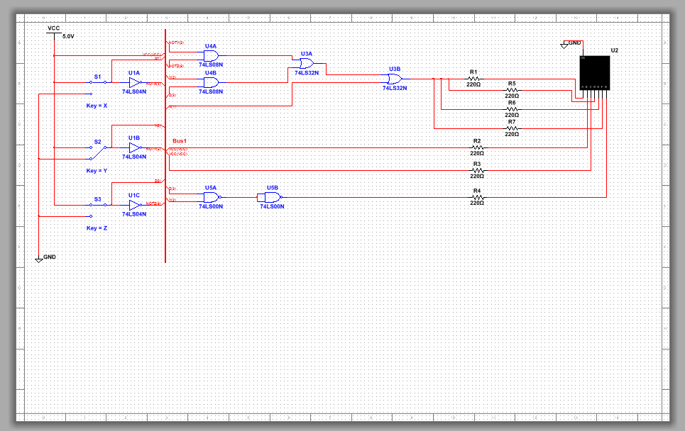
After finding every one of my logic expressions for the seven segments I then took those logic expressions and created a working circuit on multi-sim that replicates what I had to breadboard. I created this circuit in bus form as it eliminates the need for unnecessary wires and makes the circuit more appealing to the eye. Bus form works by drawing a thick vertical line on multi-sim (the bus) and by bringing the input wires on the left and connecting them to the bus when creating the circuits you can connect the wires anywhere on the bus and be able to get the input you need. In order the create this circuit I needed 2 AND gates, 2 OR gates, 3 INVERTER gates and 2 NAND gates. Since 4 gates can fit inside of a single chip I only needed 1 AND chip, 1 OR chip, 1 INVERTER chip and 1 NAND chip.
I picked the G segment to use as my NAND gate because it was the simplest circuit to create because B and C were connected right to power and did not need a circuit and the A D E and F gate was the most complicated. Since the logic expression was ZY all i had to do was use the NAND form of a AND gate which multiples the 2 inputs together, Z and Y, to get my desired output. However, it used more gates than I needed to but still required the same amount of chips to create as it would if I used AND gates and chips.
A Seven Segment display works by illuminating a certain segment on a screen that contains 7 of said segments so it can display numbers or even letters once wired properly. For this project we used a common cathode display which is wired to the ground instead of power. The purpose of the resistor before the display is so that the power used by each segment is less which saves power.
Bill of Materials
The bill of materials shows how many materials you will need to complete this certain circuit.

Bread-Boarding

Top view of my completed circuit
|

Side view of my completed circuit

|
Side view of my completed circuit
|
My second bread boarding experience went a lot smoother and faster than the first. I learned from my previous mistakes and made sure not to work too fast and make mistakes. Although, I did not color code my wires and by doing so it would have most likely saved me some time when combining inputs and outputs. When I first tested my bread boarding, it did not work properly and after looking for problems, Mrs. Z and I found it was just a loose wire that was not connected all the way. Other than the loose wire, I experiences no problems during construction and the testing of the bread board. My second experience bread boarding was definitely better and more fun then my first attempt.
Conclusion
In this project I learned how to create a circuit for a seven segment display, and also the importance of color-coding the wires, as that would make it much easier to troubleshoot if your circuit doesn’t work. At the moment I have no questions regarding the material that we had to be able to use to be successful in this project. We also learned the importance of K-mapping, as in this instance with multiple mini-circuits in one big circuits, it would be a lot easier to just do a k-map for each rather than doing 7 sets of Boolean algebra simplification with 6 different midterms each.
