Project Overview

|

|
The circuit designed in this problem was intended to create a majority vote machine for a board of directors to eliminate controversy. The board of the directors consists of a President, a Vice President, a Secretary and a Treasurer. We were constrained by the gates we were allowed to use, which were only 2 input gates and we were only allowed to use AOI logic gates which are AND, OR and Inverter gates. Also, in the event of a tie, the president of the board is the tie breaker, if he votes yes the decision passes and if he votes no the decision fails.
Problem Conception via Truth Table and Un-Simplified Expression

|
The purpose of the truth table is to show which situations will cause the decision to pass. The number of columns in the table is determined by the number of variables and since there are 4 members of the board of directors there are 4 variables (P= President, V=Vice President, S=Secretary, T=Treasurer). The number of rows in the table is determined by the equation 2^n where n is the number of variables. Since there are 4 variables, 2^4 equals 16 rows. The output of the truth table will either be a 0 or a 1, if it is 0 that means the decision failed and if it is a 1 that means the decision passed. The truth table explains what happens in the event of a tie as shown in row 10 where the President and the Treasurer voted for the decision to pass and the Vice President and the Secretary voted for the decision to fail, resulting in a tie. However because the President voted for the decision to pass and it is a tie, the decision gets passed.
The un-simplified expression, shown at the bottom of the truth table, is
Output=P'VST+PV'S'T+PV'ST'+PV'ST+PVS'T'+PVS'T+PVST'+PVST. The way you can determine this is by every time the decision passes (when the output is 1) you look down the columns for each variable and if you see a 0 underneath that variable is off or is NOT that variable, so it gets a line over it or a ' mark. If the variable has a 1 then the letter remains the same and you just multiply it into the output expression. The un-simplified expression is a Sum of Products (SOP) expression because they are all individual scenarios when the decision could pass and so each output expression is added to each other making it a SOP expression. |
Un-simplified Circuit
|
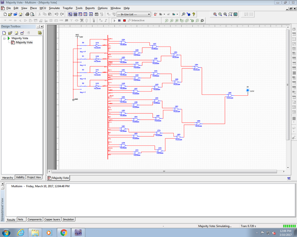
This is the un-simplified circuit that I created on MultiSim to simulate the majority vote circuit. I created this using a bus which makes the circuit look less busy because it eliminates the need for more wires. The un-simplified circuit requires the need for many gates which are unnecessary and that requires the need for more chips which are also unnecessary. In total there are 35 AOI gates: 4 Inverter gates, 24 AND gates and 7 OR gates and you would need 1 Inverter chip, 6 AND chips and 2 OR gates to build this circuit.
|
|
Boolean Algebra Simplification
In order to simplify a logic expression, you must use Boolean Algebra. The steps to come up with the simplified expression are shown below.

Simplified Circuit
|
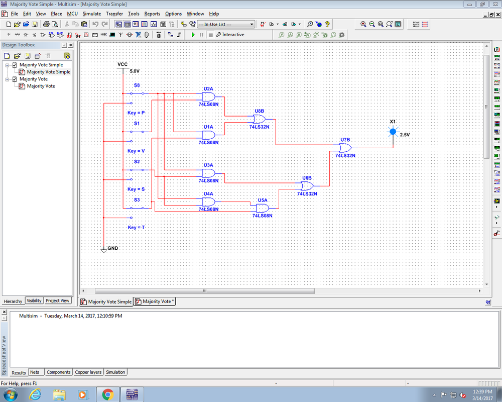
This is the simplified circuit I created on MultiSim using the simplified logic expression. It is not in bus form because this circuit requires a lot less wires than the un-simplified and therefore is not as messy as the un-simplified would be if not created with a bus. As you can see the simplified circuit does not require as many gates and chips as the un-simplified circuit. In total there are 5 AND gates and 3 OR gates which would require 2 AND chips and 1 OR chip to construct, which is much less than the required number for the un-simplified circuit.
It is important to have less chips and gates because it can save money, is easier to construct and does not take up all the room the un-simplified circuit did. There are 27 less gates and 6 less chips in the simplified circuit that in the un-simplified circuit and that makes a huge difference.
|
|
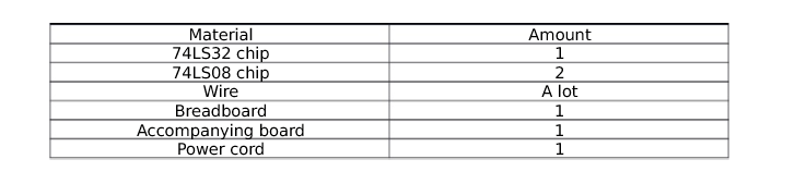
Bill of Materials
Breadboarding
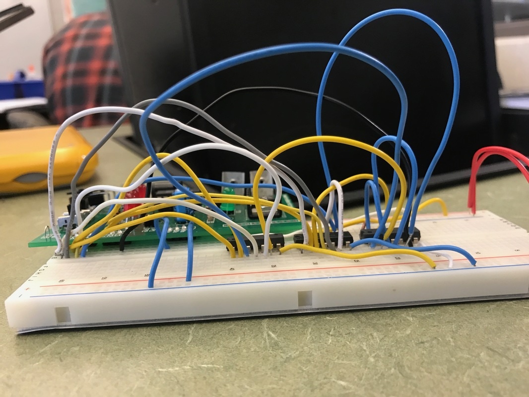
This is the side view of my completed majority vote circuit

This is the top view of my circuit halfway through construction
|

This is the top view of my completed majority vote circuit
|
Conclusion
This is an important project because it teaches us students how to bread board and how to simplify circuits and logic expressions.
My first bread boarding experience went better than I expected it to go. I rushed through the wiring the first time so the first time I tested it the circuit did not work however when I looked back to see what mistake I made I realized I made a simple mistake. I did not ground one of the chips and it was most likely because I rushed through construction. However besides that one mistake, the circuit worked on my second attempt. From this project I learned not to rush through projects and take my time to make sure it is right the first time so I do not have to search every wire to find the mistake. Although overall I enjoyed my first bread boarding experience and learned some valuable lessons for future bread boarding projects.
