Featuring Andrew Burke

Project Description
The purpose of this project is to test a pre-built engine mount provided by PLTW under different conditions an aircraft might encounter. The constraints of the project were that the mount had to support one Lycoming O-300 engine (250 lb.), the forces that we had to apply on the frame which were -3Gs +6Gs and the normal force of gravity, the maximum diameter for the ANSI pipe was 1.5 inches and finally we could not alter the design of the engine mount. These constraints made the project more difficult however my partner and I were able to overcome the challenges and we were able to successfully test the frame under all the conditions.
Gantt Chart

A Gant Chart shows an estimated timeline of when my partner and I would like to accomplish certain parts of our project. Tuesday we went on a field trip as a class so no one got to work on the project.
Procedure
First my partner and i completed an assignment of material properties in order to better understand which material would be the best to create an airplane frame. Then we went through two other activities that taught us how to create frames in Inventor and how to perform a structural analysis on a frame. The outline for the frame itself was already given to us by PLTW, we had to pick what materials to make the frame out of and how thick to make the pipe walls. We decided to go with the thicker pipes made of steel in order to have as little moment as possible when the engine mount went through these tests. We went with steel because steel has both a high tension and high compression strength, which would be required to hold up the 250 lb. engine at 6 and 3 Gs. Once we added the pipes in around the sketched lines, we had to form them so that no ends were sticking out of flat faces and that they all fir together nicely where they came together. In order to prevent the pipes from sticking through flat faces I used the trim to face option, which cut the pipes to the selected face. to make the pipes fit together nicely I used the miter tool which cut the pipes in a way that they fit together, and did not overlap in the design. In order to run the test we then had to constrain the frame, we decided to fix all the points where the struts touched the mount wall, as this would prevent them from moving around.
Calculations
Solution
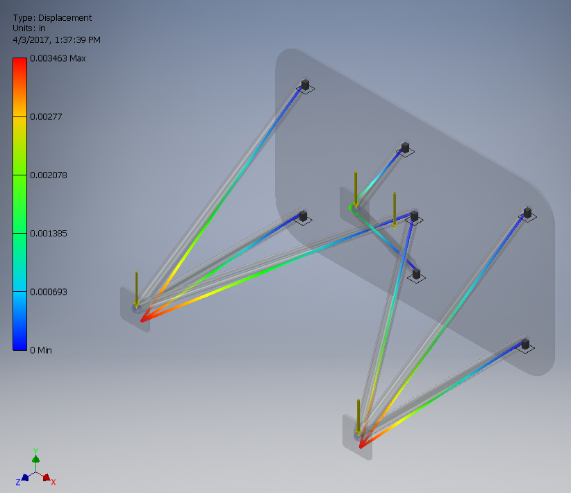
Frame in normal gravity
|
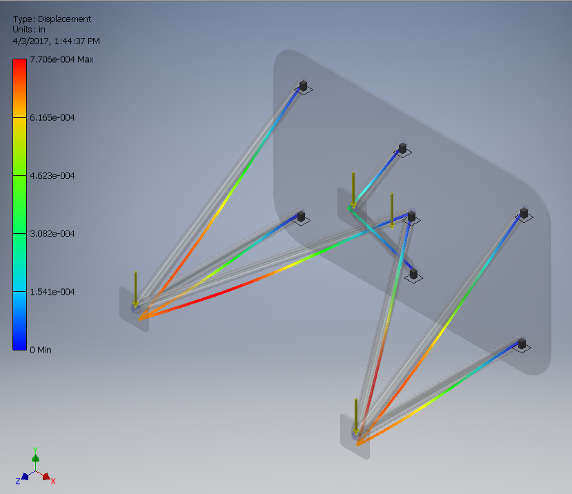
Frame under +6Gs
|
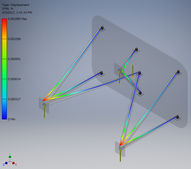
Frame under -3Gs
|
The testing that we completed applied the forces specified above (regular gravity, negative 3Gs and 6Gs) to the frame to see how effective our frame was at holding the engine in place under extreme circumstances. In addition to the forces applied to the engine mount points we also had to fix the pieces where the struts touch the engine mount base plate, in order to restrict their movement. Our design meets the constraints because the pipe was the right diameter, and we used the correct base weight for the engine and the correct G levels for the other two tests. The material we chose for the pipes was steel, as it has very high tension and compression strength, and the frame would be under both tension and compression at points, with the magnitude of the test forces we decided to go with steel, as it is also quite cheap and easily molded.
Conclusion
- In this project I learned how to create frames in inventor using 2D sketches, and also how to conduct an analysis of the frame using different forces in different positions. I also learned the different characteristics that some common building materials have.
- My contributions consisted of doing the frame and testing on inventor. Kyle was in charge of completing the Weebly, and we decided to split the work in the report so that it balanced out the fact that the Weebly was more work than inventor.
- I do believe that the frame generator is quite useful to aerospace engineers as it provides an easier way to shape a frame that is proven to work in a way that it can be used for multiple types of aircraft, and it eliminates the need to create a new frame from scratch for each project.
